Mesh Editing & Texture Mapping
Part 1: Fun with Bezier Patches
In part 1, I pre-processed matrix of Berstein polynomial coefficients for use in BezierPatch::evaluate(...). My reasoning for this was that in evaluating the Bezier patch, a pre-processed matrix will multiply out more efficiently than recursively calling De Casteljau's algorithm. (And, it's slightly less complex to implement!) Then, inside evaluate(...), I calculated the variable vectors uVect and vVect of the Berstein polynomial, and dotted those vectors with the coefficient matrix to get the actual Berstein polynomials, ut and uv. The u-directional polynomial then multiplies with the 4 sets of 4 u-oriented control points of the Bezier Patch to interpolate for a set of 4 v-oriented "secondary" control points. Finally, the v-directional polynomial is multiplied with the secondary control points, returning the 3D point at (u,v) on the Bezier patch.
In add2mesh(...), I evaluate a Bezier Patch and tesselate the patch uniformly on to an 8x8 grid with 128 triangles. I iterate integer-wise (to avoid accumulating error) using 2 for-loops to cover an 8x8 grid. On all of the unit grids, I first evaluate the Bezier Patch for the top-left, bottom-left, and bottom-right points and pass those 3D points into addTriangle(...). Then, as a slight optimization, I only need to further evaluate the Bezier Patch for the remaining top-right point; I pass those points into addTriangle(...).
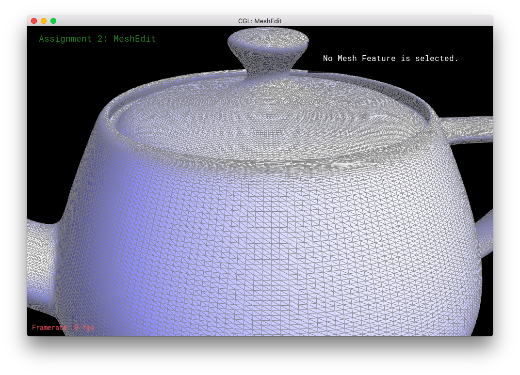
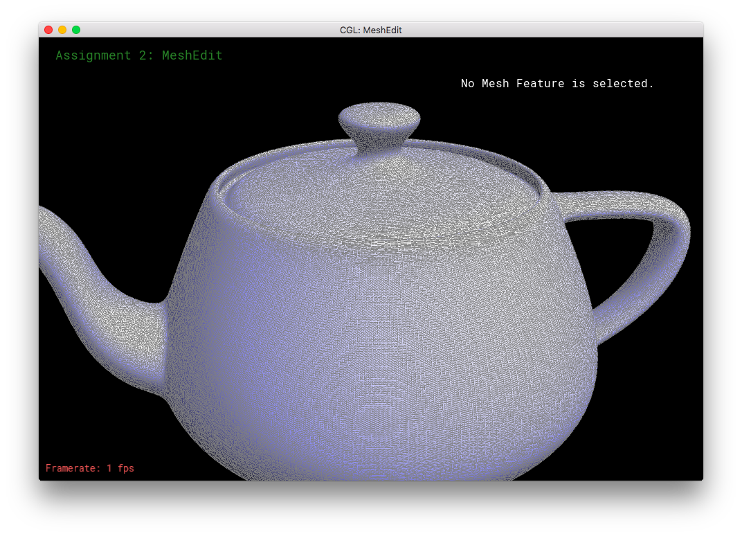
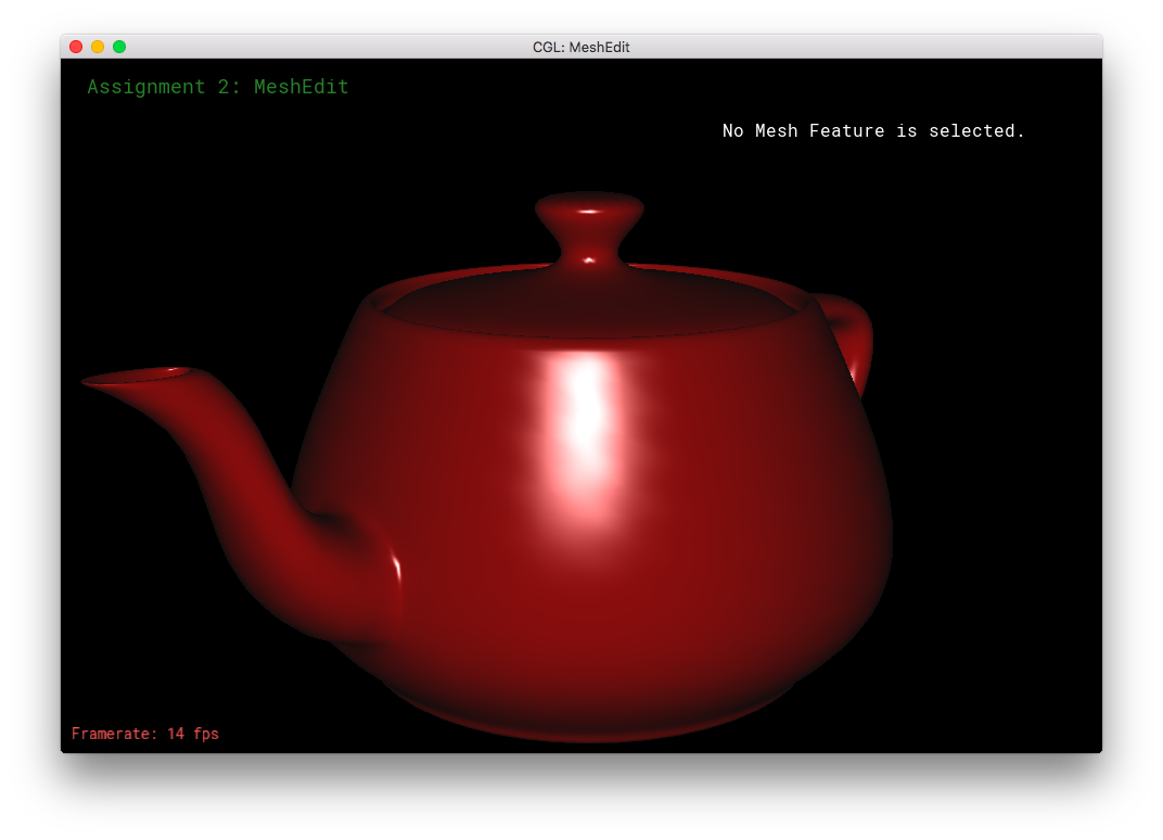
BezierPatch::evaluate(...) and add2mesh(...) seems to work!Part 2: Average normals for half-edge meshes
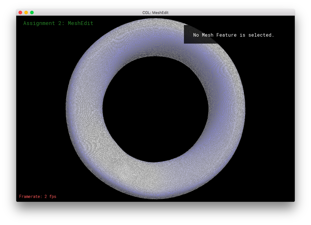
In Part 2, I computed the area-weighted unit normal for a given vertex. In computing an area normal, you need to cross-product two vectors, both of which are based on the given vertex and point towards the given vertex's neighbors. Because the half-edges are oriented counter-clockwise on a surface, the traversal of the nieghboring vertices happen in a clockwise fashion. (Due to the h_twin = h->twin(); h = h_twin->next(); algorithm.) So to obtain positive products from the cross-product, one has to take the vector_(given vertex to new neighbor) X vector_(given vertex to old neighbor).
Before looping, I first initialize an "old" vector by subtracting the first neighboring vertex's position with the given vertex's position. Then I traverse the neighboring vertices: computing the "new" vector by subtracting the new neighbor's position with the given vertex's position; crossing the "new" and "old" vectors, adding that product to a running sum vector; and updating the "old" vector to have the "new" vector's value. After terminating the traversal, the normalized vector of the running sum is returned. That normalized vector is the area-weighted unit normal for the given vertex.
The traversal algorithm can handle vertices on boundaries. Boundary halfedges do not mess up the traversal, h->twin()->next()->vertex() correctly gives a valid vertex even if the vertex is on a boundary. Vertices on boundaries are still valid and have 3D positions.
Part 3: Edge Flip
In Part 3, I implemented HalfedgeMesh::flipEdge(...), which flips the edge that is passed in and returns an iterator to that flipped edge. First, I check if the edge is on a boundary: if it is, then the passed-in edge is returned immediately. Otherwise, it is safe to flip the edge!
I drew a diagram of the edge flip in the code, to clarify the function for myself and for potential readers.
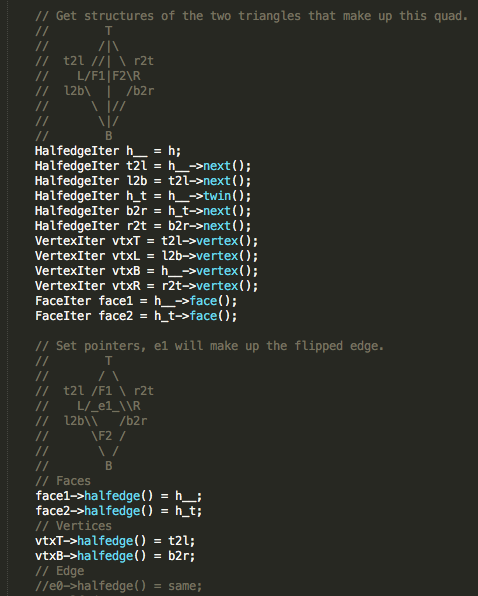
Because we are only flipping an existing edge, and not creating any new elements in the mesh, we do not need to call any of the new*() functions. To prepare for the edge flip, I get all of the necessary data structures. Then I reassign the structures accordingly: the given edge still points to the same halfedge, but the corresponding two halfedges have their vertex()'s and next()'s changed. Likewise, the face()'s of some strucutres are changed. To ensure correctness, the halfedge()'s of the top and bottom vertices are reassigned, in case they used to point at the given edge's halfedges. The next()'s of all of the involved halfedges are reassigned. Note that the left and right vertices' halfedge()'s do not have to be reassigned. A vertex only has to store one of it's halfedge()'s; the old halfedge()'s are still valid assignments.
Part 4: Edge Split
In Part 4, I split edges! Two triangles with on shared edge is split into four separate triangles. This part similar to part 3, except now we have to allocate new elements into the mesh. Again, I drew diagrams in the code to help visualize the need assignments of the structures.
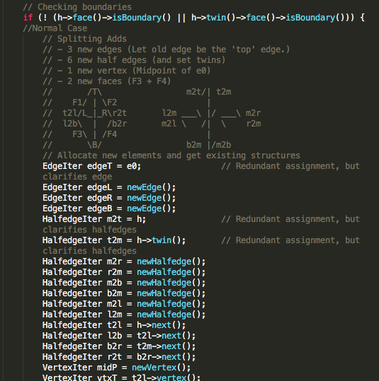
Basically, what I did for this part was the same as in Edge Flip. I first get all the relevant data structures. But then this time, I also allocate new structures by calling new*(). Then, I calculate the midpoint's position - it is the only new structure that requires a position assignment. Then, I go through the vertices, faces, and edges to set their appropriate halfedge()'s. Finally, I use the halfedge's setNeighbors(...) function compactly set each halfedge's pointers (iterators). While some of the assignment in setNeighbors(...) is redundant, it ensures correctness by requiring everything to be updated.
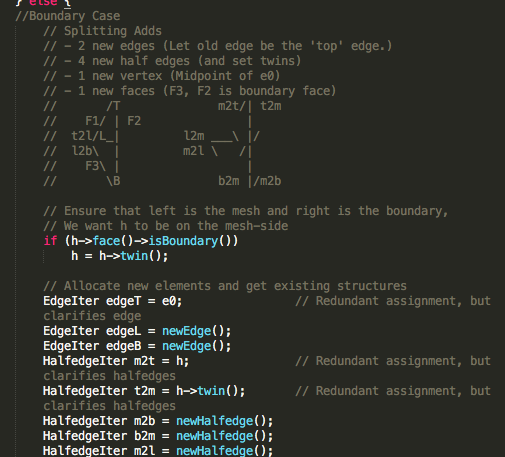
I also handle the case where the edge to be split is on a boundary. In that case, less new structures are allocated into the mesh, but assignments are slightly trickier. Only the non-boundary face is split into two and receives a new edge; the boundary face is left alone. At the start, before getting the relevant data structures, we obtain h such that h is not on the boundary. This orients the triangle so that the face to be split is on the left side of the given edge, and the boundary face is on the right side of the given edge. Then, we obtain the relevant structures and the correct assignments.
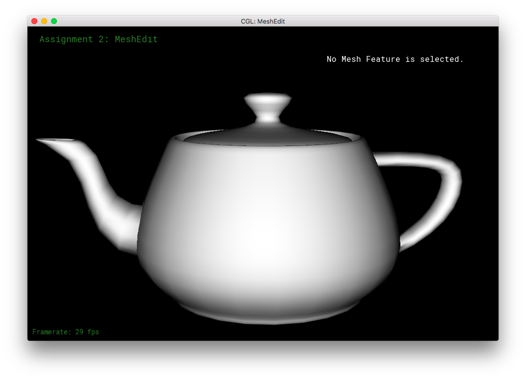
Part 5: Upsampling via Loop Subdivision
Conceptually, upsampling was a bit difficult for me to understand and get started with. However, after looking through the documentation in student_code.cpp and halfEdgeMesh.h, things became much clearer. The actual implementation of this part was decently quick, except for a bug I ran into.
In implementing upsampling via loop subdivision, I mostly just followed the TODO comments. First, I compute the new positions for all of the vertices in the input mesh, and mark their isNew as false. As for computing the positions based on the loop subdivision, I precomputed the fractions in the formula and assigned exact decimal values rather than assigning fraction to the variables. This should slightly increase numerical accuracy, and fairly improve performance by reducing the number of computations per vertex.
Then, I computed the updated vertex positions of the edges and stored the values in the edges' newPosition. The values stored will become the positions of the newly allocated vertices from subdivision/edge-splitting. Again, I have the formula's fractional formulas pre-computed. Here, I mark the edges' isNew as false. In this section and the next, I drew small diagrams in the code comments for clarification, as in the previous parts.
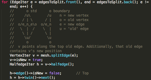
Then, I split every old edge of the mesh. The old edge becomes the "top" edge of the split quad. The "left" and "right" edges are marked isNew as true, since they are new. However, even though it is newly allocated, the "bottom" edge is marked isNew as false, since it was originally part of the old edge. For the purposes of edge-flipping, it is an old edge. The newly created midpoint-vertex for each subdivision, returned by splitEdge(...), is marked as isNew true.
In this edge splitting section, I had to figure out how to iterate and split all of the edges of the original mesh and none of the new edges created by the splitting. This task was tougher than I realized, as it turned out that mesh.edgesEnd() returned an iterator and not a real reference value. This had the strange effect that the end variable increased whenever an edge was split, even if I only assign the end once as mesh.edgesEnd() once before the loop. Thus the end was every-increasing, leading to an infinite loop. So, while iterating through the original edges in the previous section (Computing the newPosition values), I add the edge to a list of EdgeIterss, called edgesToSplit. Then in this splitting section, I iterate through the list of EdgeIters, rather than through using the iterator provided by mesh.edgesBegin() and mesh.edgesEnd(). The list is finite and does not grow with each splitting.
In the next section, I flip any edge that connects to an old vertex and a new vertex. To do this, I iterate through all edges of the newly subdivided mesh. If the edge was part of an old edge, with isNew marked as false, immediately skip to the next iteration. Otherwise, the edge is new. So, we check whether it's vertices are of opposite isNew-ness, and flip the edge if they are: the two vertices are accessed via the edge's halfedge and the corresponding twin. If one if the vertices has (isNew == true) and the other has (isNew == false), we flip that edge. This operation ensures that the triangles are loop subdivided into equilateral-like shapes, rather than being overly skinny. (As explained by Denis Zorin's diagram in the assignment spec.)
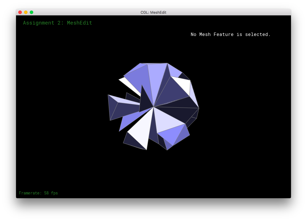
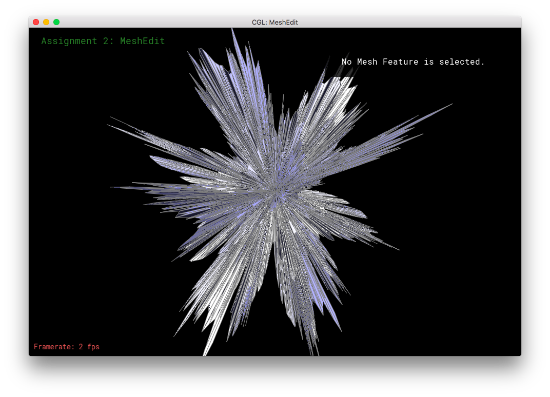
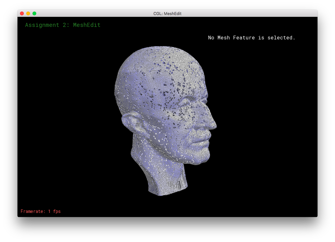
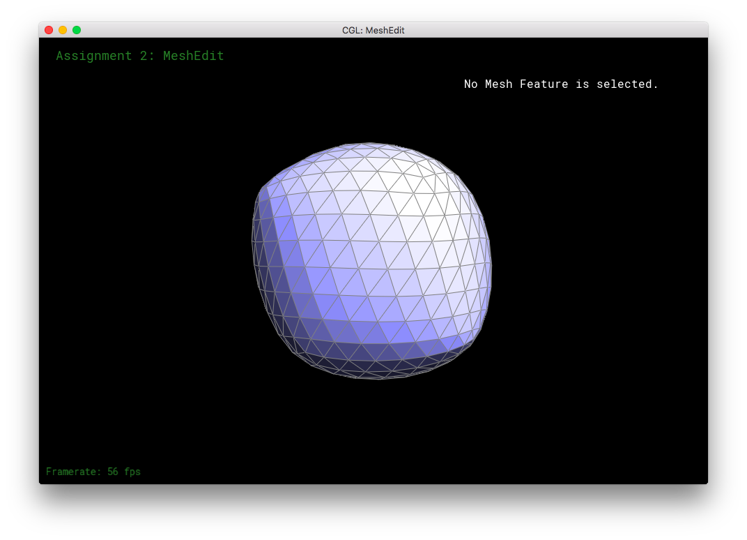
Finally all of the vertices' positions are updated. If the vertex is an vertex from the old mesh, with isNew false, it's position is updated with the value stored in the newPosition variable. Otherwise, if the vertex isNew, we assign it the value that was stored in it's old edge's newPosition variable. By construction of the previous parts' functions, the new vertex should naturally point to a halfedge whose edge contains the correct corresponding newPosition value. However, a small bug arose in my code. My new vertices did not all point to the correct halfedge whose edge had the newPosition value. I suspect that is becase my edge-flipping function "unstably" reassigns the vertices' halfedges, without respect to whether they are new or not. (This bug created interesting patterns in my meshes though.) To account for the "unstable" edge flip, I have an extra condition/loop inside this section. I have a HalfedgeIter traverse the incident edges to the vertex. The traversal stops when a non-New non-Zero-newPosition edge is found -- which is guaranteed to exist because it is exactly the edge that the new vertex was supposed to point to, before the edge flipping. This resolved the bug and thus subdivision happens correctly
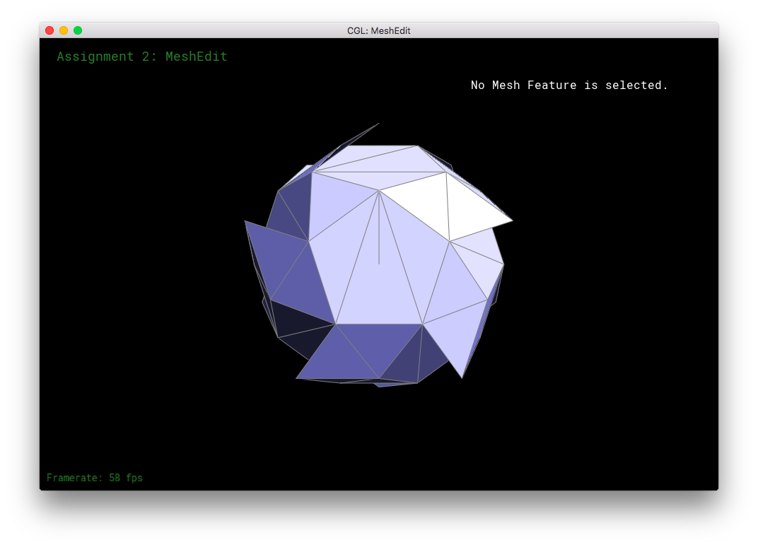
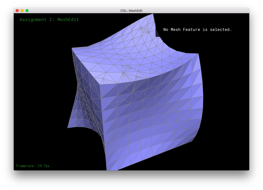
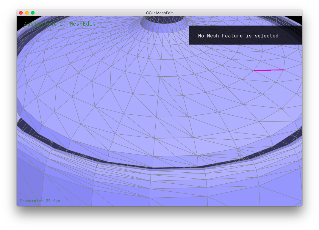
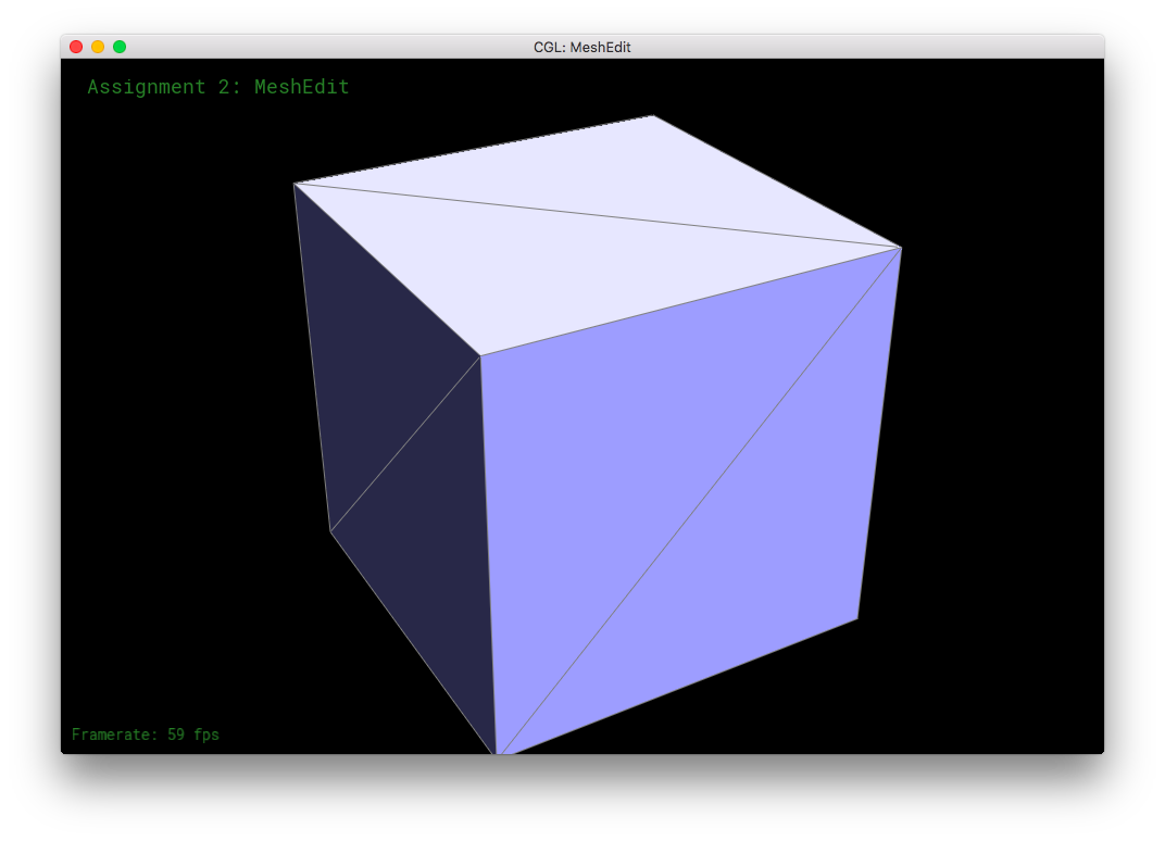
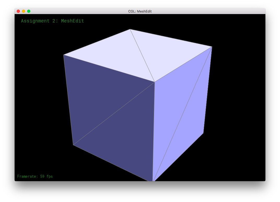
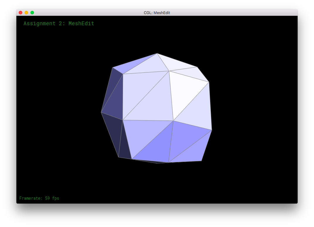
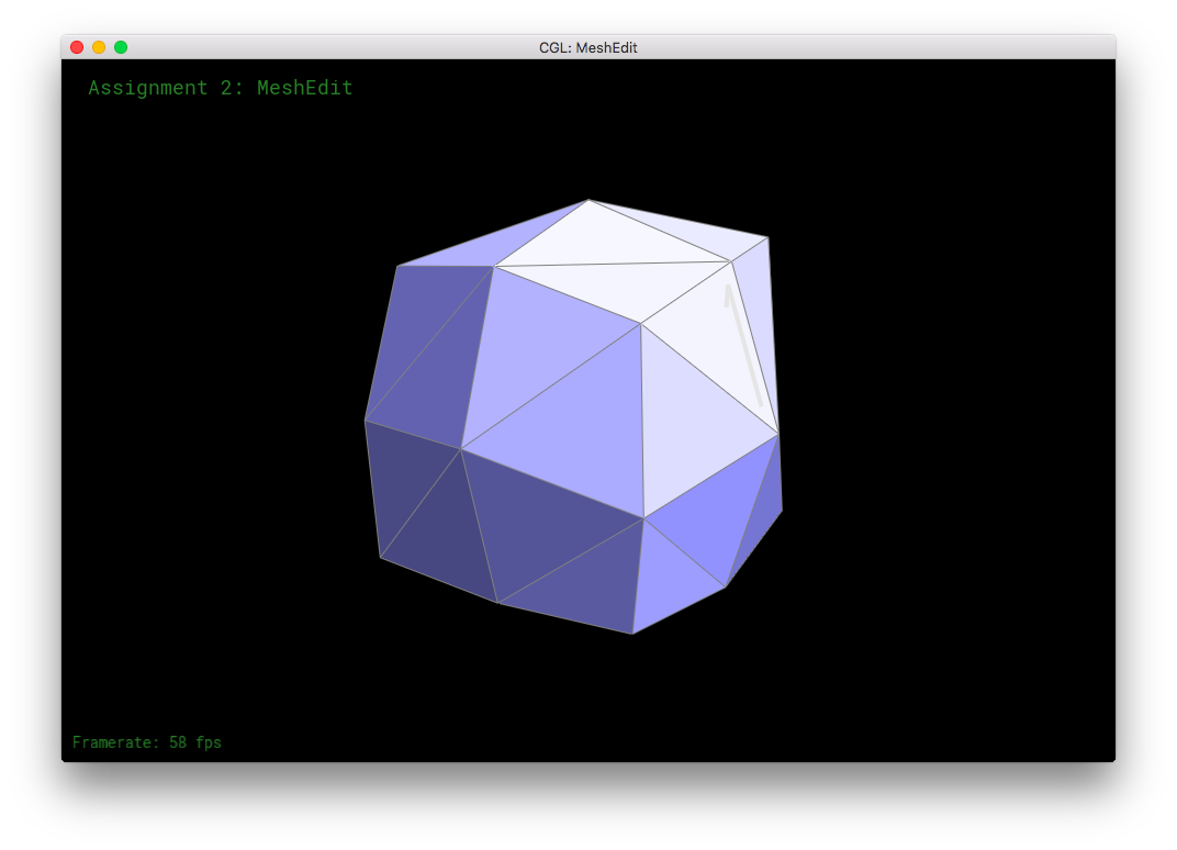
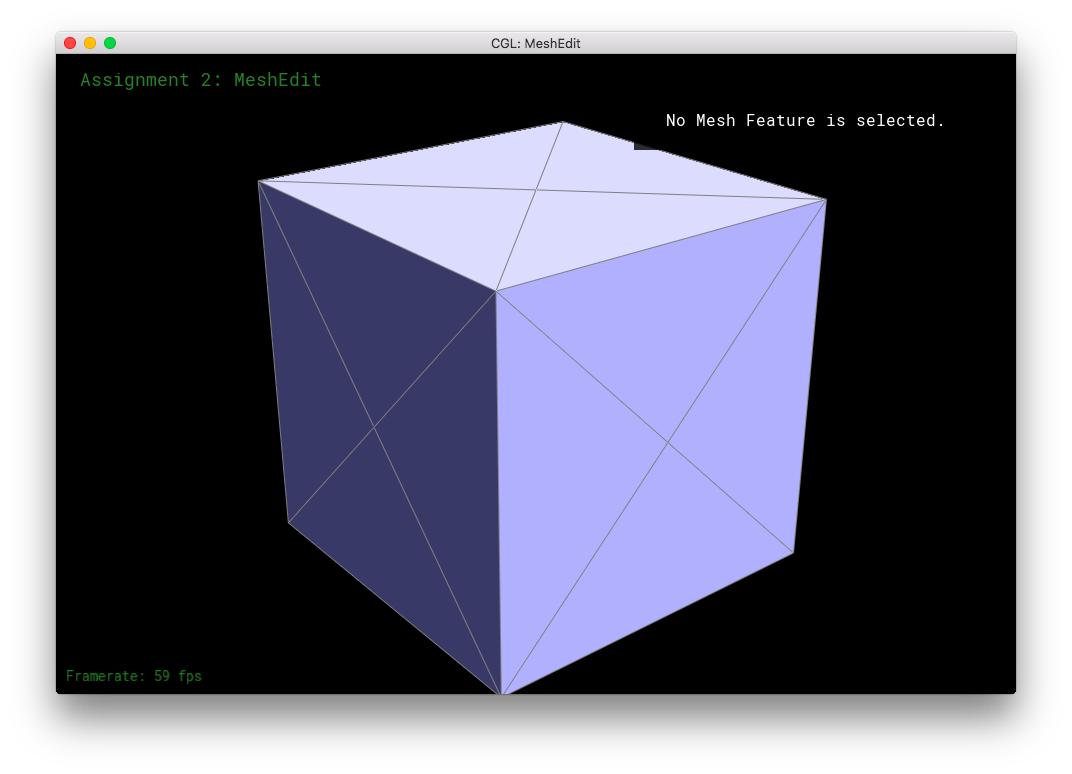
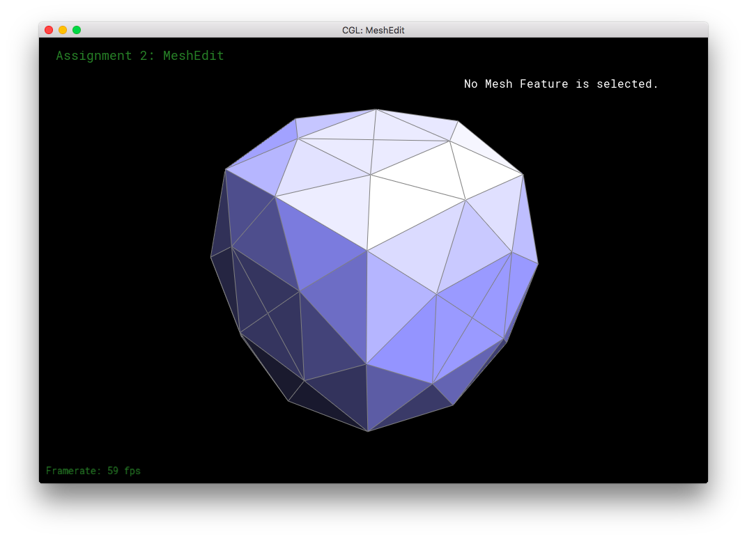
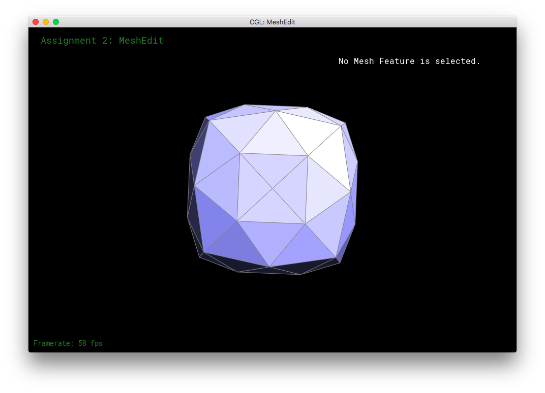
Here, I tried subdividing cube.dae. After several subdivision, the cube takes on an asymmetric shape.
This arises because of the original mesh topology on the cube. The subdivision algorithm smoothes out vertices higher degree more than vertices with lower degree. So, in the low-poly cube, the higher degree vertices get smushed together moreso than the low degree vertices, leading to asymmetry. This asymmetry in subdivision can be solved by equalizing the vertices' degrees as much as possible before subdivision. Simply flipping edges before subdividing will not solve the problem: the original topology only has a limited amount of edges to go around, some vertices will always have a different degree than other vertices. The subdivision would produce an asymmetric mesh in that case. However, one can also split the cube's face edges before subdivision. The splitting of the edges can be used to equalize the degrees of all the original vertices. This allows the mesh to subdivide symmetrically. When the cube's respective symmetric vertices have the same degree, the cube subdivides symmetrically.
Part 6: Fun with Shaders
In part 6, I had fun with shaders! One of the more annoying parts of this section is type-matching: that everything is in floats and nothing takes ints.
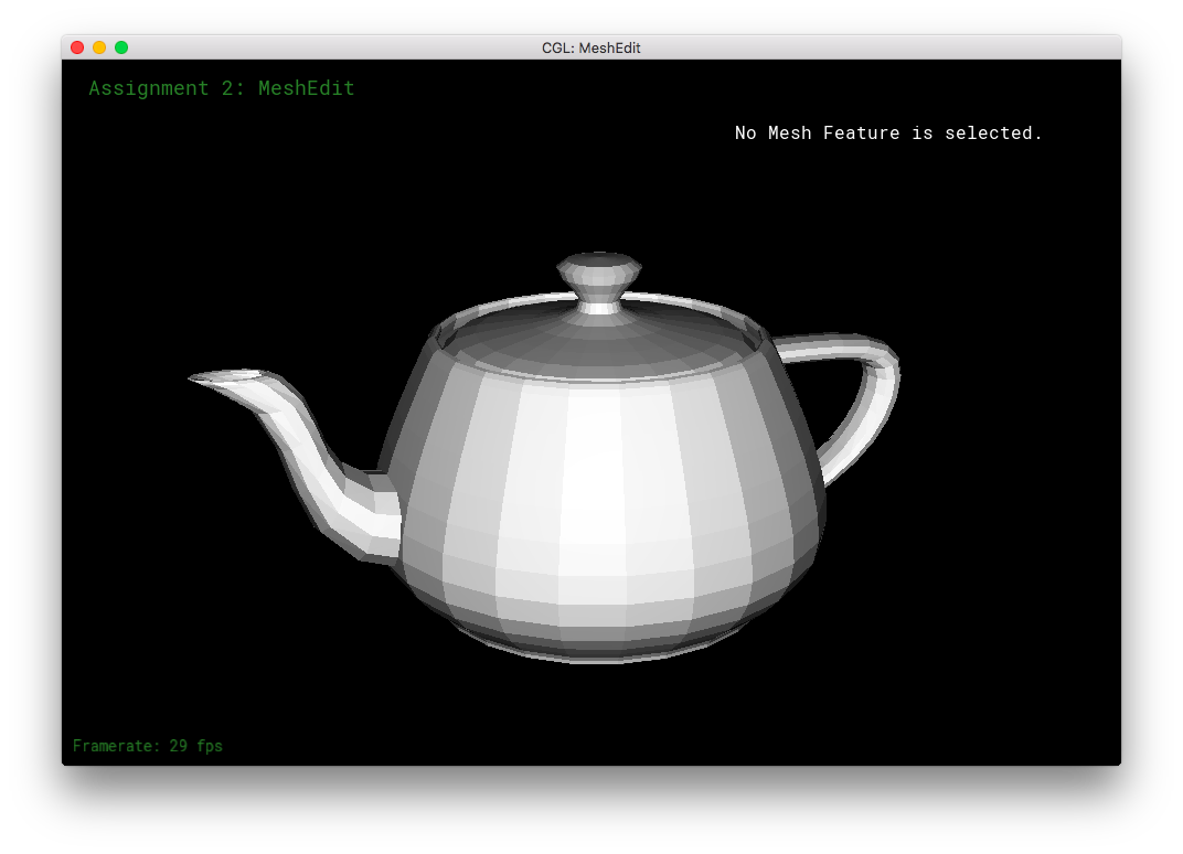
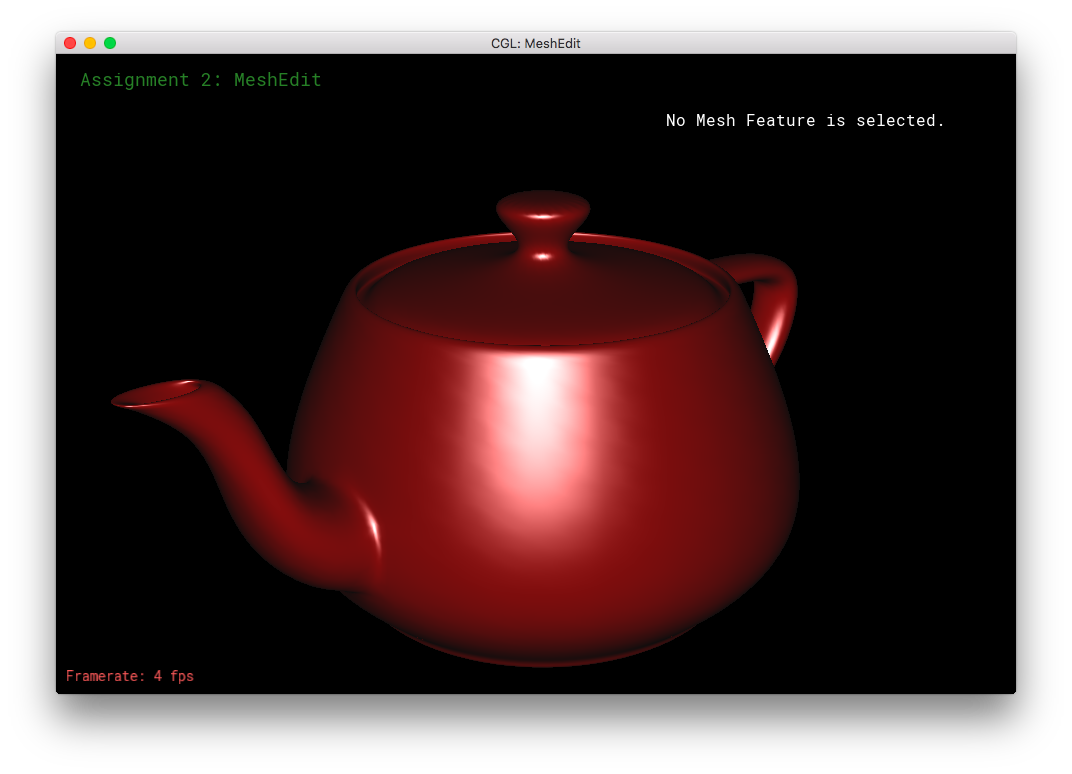
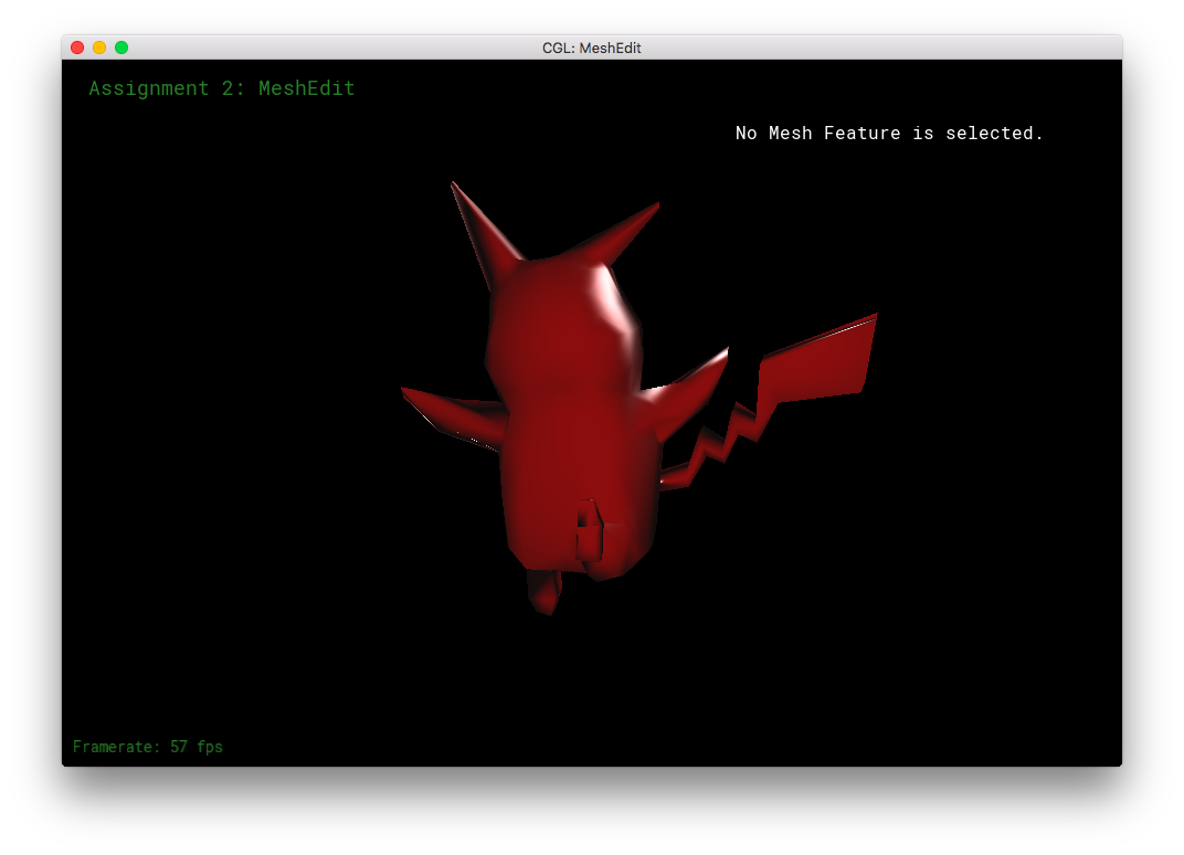
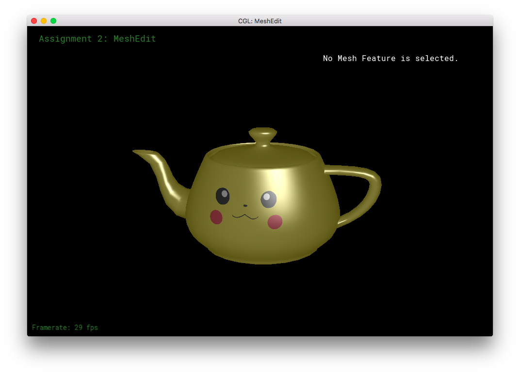
I simply referred to the given formulas and the lecture slides to implement this part. For Phong shading, I calculated the light direction vector, reflection direction vector, and the eye direction vector. Then, I used those values to calculate the specular highlights: specular is first the max of (reflection direction dot eye direction, and 0.0), then the specular is raised a certain power and multiplied by a certain coefficient. (I defined spec_power as 8.0 and spec_coeff as 1.0 at the top of the frag file.) The diffuse light is the absolute value of eye direction dot the normalized normal. The ambient light was chosen as a very dark gray. Phong shading adds together the specular, diffuse, and ambient lights.
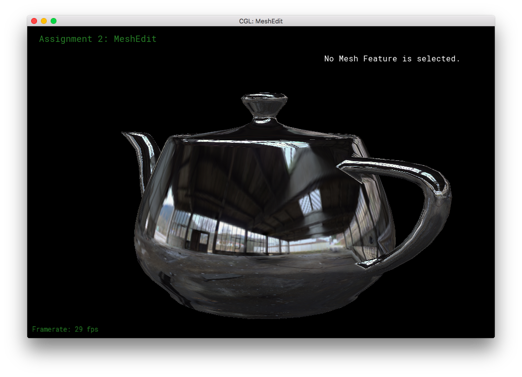
This section was fairly straight forward. For environment mapping, I calculated the reflection direction as given by the formula in the specs. Then, I calculated theta and phi as according to their 3D geometric meanings, using the atan(2) and acos() functions. Then, I converted theta and phi to uv-coordinates using the other forumula in the spces. The uv-coordinates were then passed into texture2D of the envmap, in order to obtain the corresponding texel color. The color is returned for texture2D as an RGBA value, so I had to convert it to the corresponding RGB value, before finally returning the vec3 color.
I did quite a bit of extra credit work for this part and the next part combined, so I'll put that into a new part by itself! It's below Part 7 below.
Part 7: Design your own mesh!
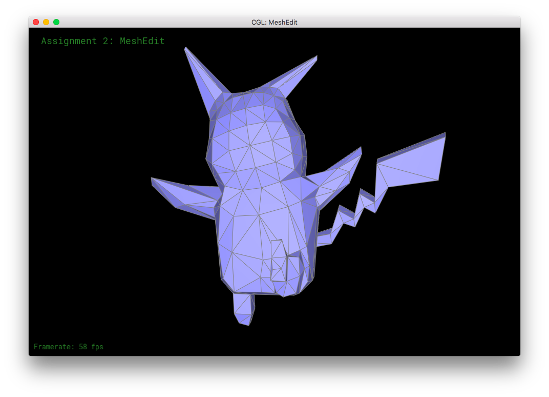
This part required that I use a mouse, but even then the controls were difficult to learn. In other applications, I had been used using LMB to select and drag select items, using RMB to deselect items or to rotate the view. So, it took me a long while to adjust to using RMB to select and drag, LMB to confirm, and not having a mouse button to automatically/fully deselect items. (I had to use weird combinations of command, control, and shift.) That being said, this part was incredibly fun. Though, great patience is required to be able to adjust all of the vertices, edges, and faces, to exactly how one pictures it. I have a newfound respect for professional 3D modelers. Even though I had an image in my mind, it was difficult to produce a model that remotely resembled my original idea.
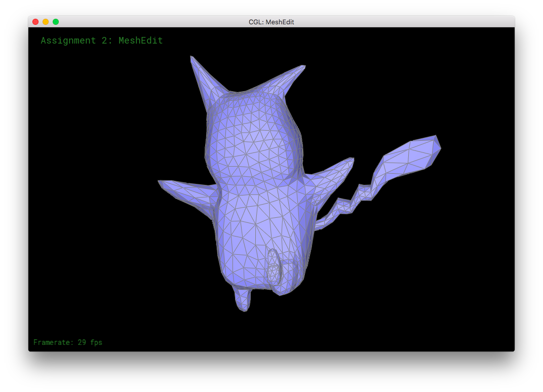
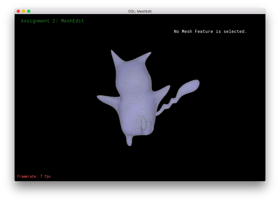
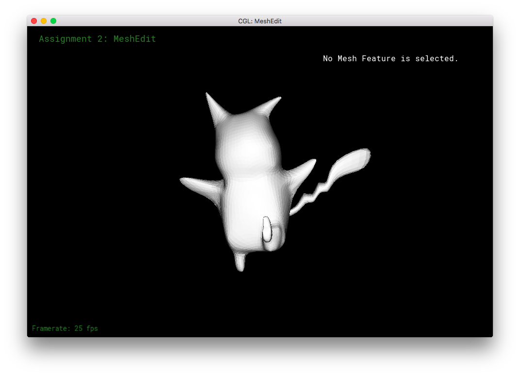
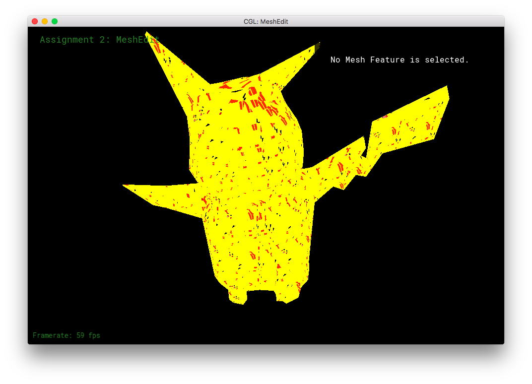
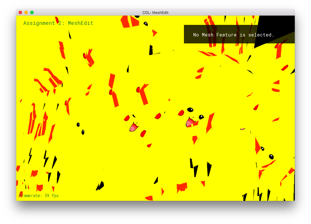
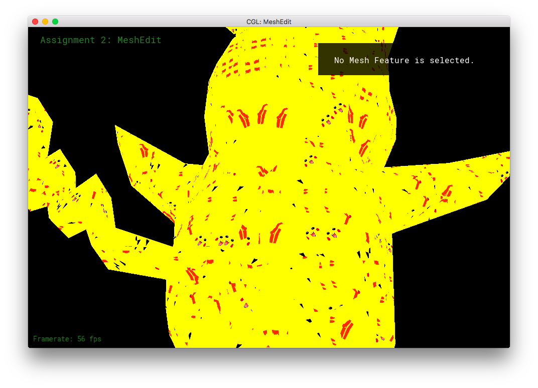
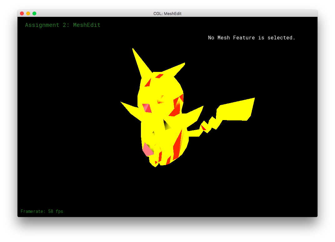
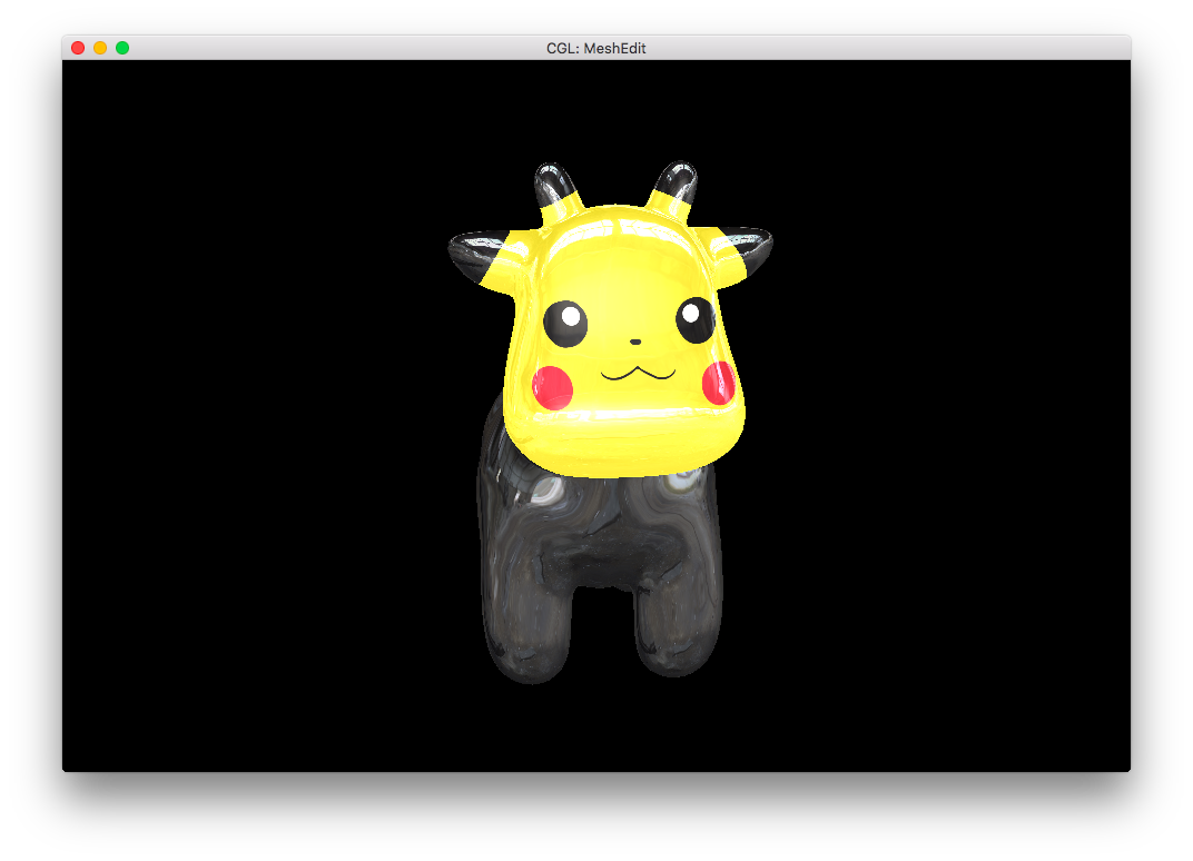
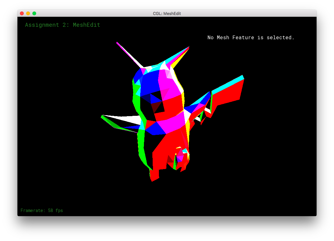
I made a 3D Pikachu! (Sort of. It's not particularly spectacular.)
Part 8: Extra Stuff from Part 6 and 7!
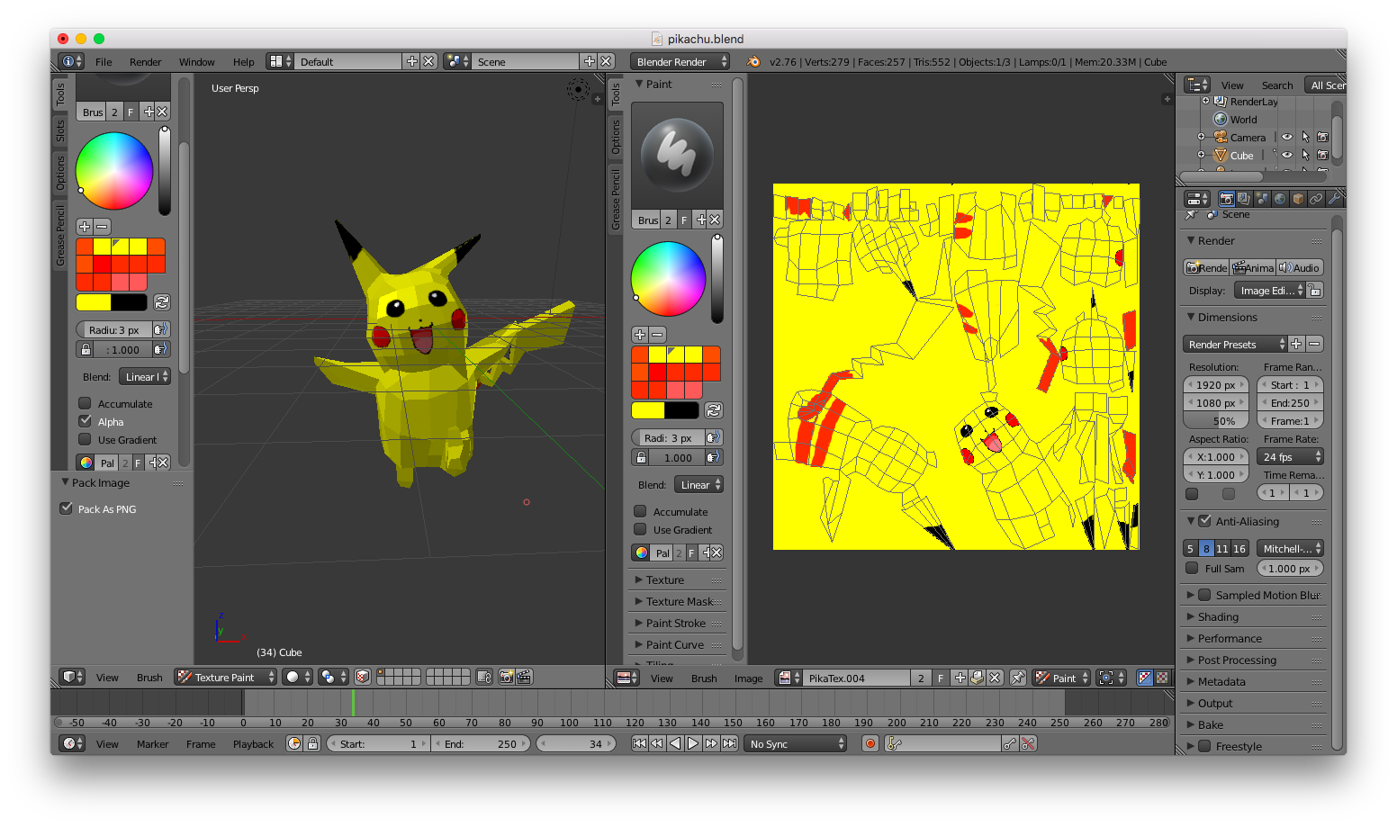
I uv-unwrapped my Pikachu mesh in Blender, and 3D texture-painted it.
However, I made some extra shaders!
For this part, I had to do some digging through the other code files. I had to make the renderer/shader program load extra textures! In main.cpp, new textures were loaded with (GLuint tex = makeTex(FILE_PATH);), followed by a glActiveTexture and glBindTexture. In meshEdit.cpp, the corresponding textures were labeled through (glUniform1i(glGetUniformLocation(shaderProgID, NAME), VAL);). This allowed me to have uniform sampler2D NAME at the top of my frag file, which in turned allowed for the sampling of texels through vec4 texture2D(sample2D tex, vec2 uv).
With the power of fancy new textures, I made some extra shaders in frag:
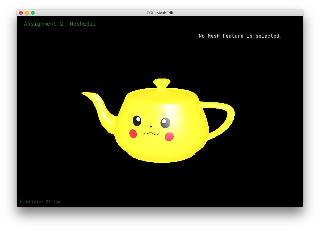
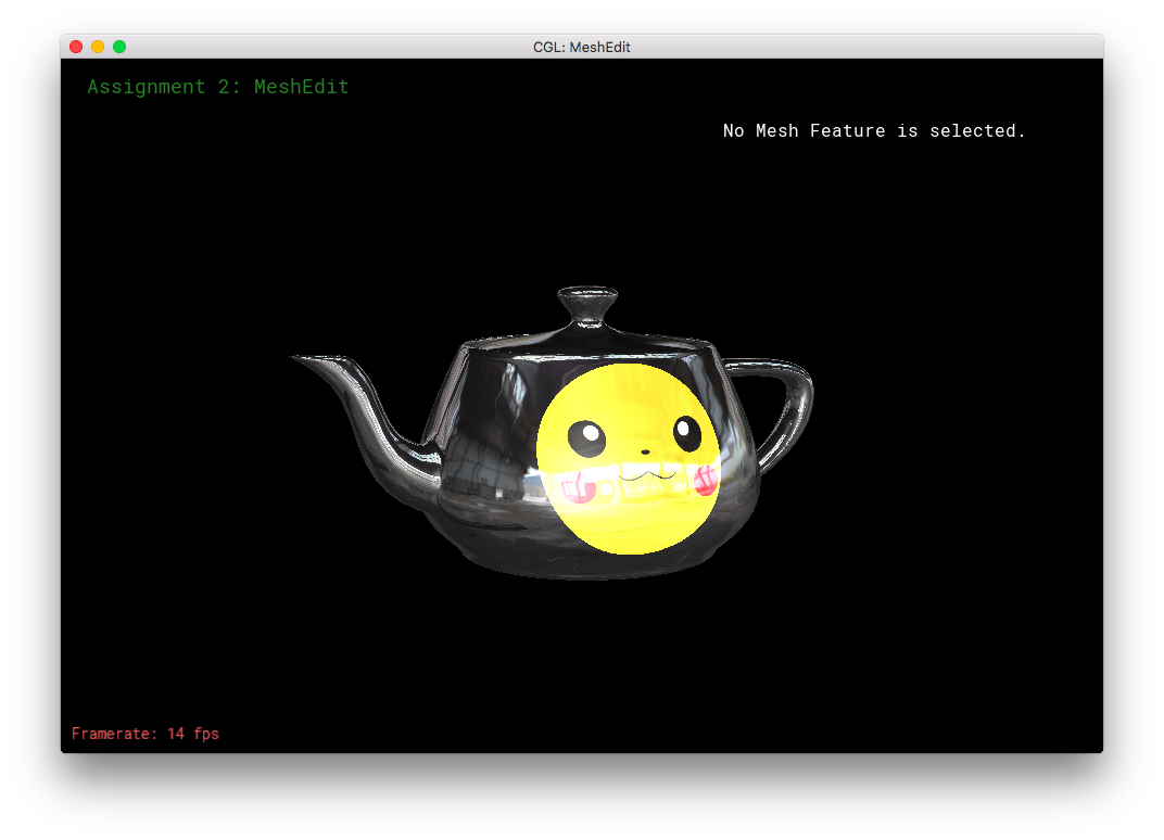
I made a Pikachu face texture for the teapot. (This is a different texture than the UV-mapping from Blender).
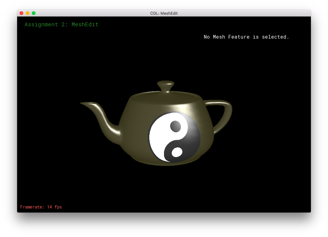
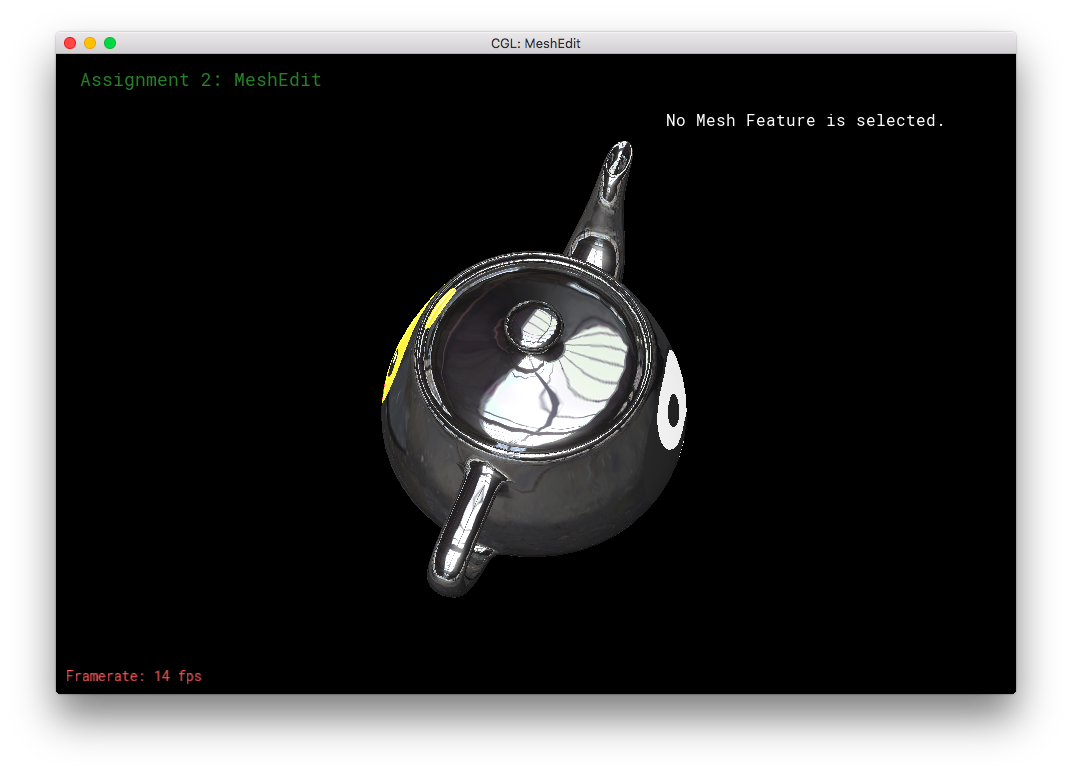
I also made my own version of Weilun's YinYang shader/texture!
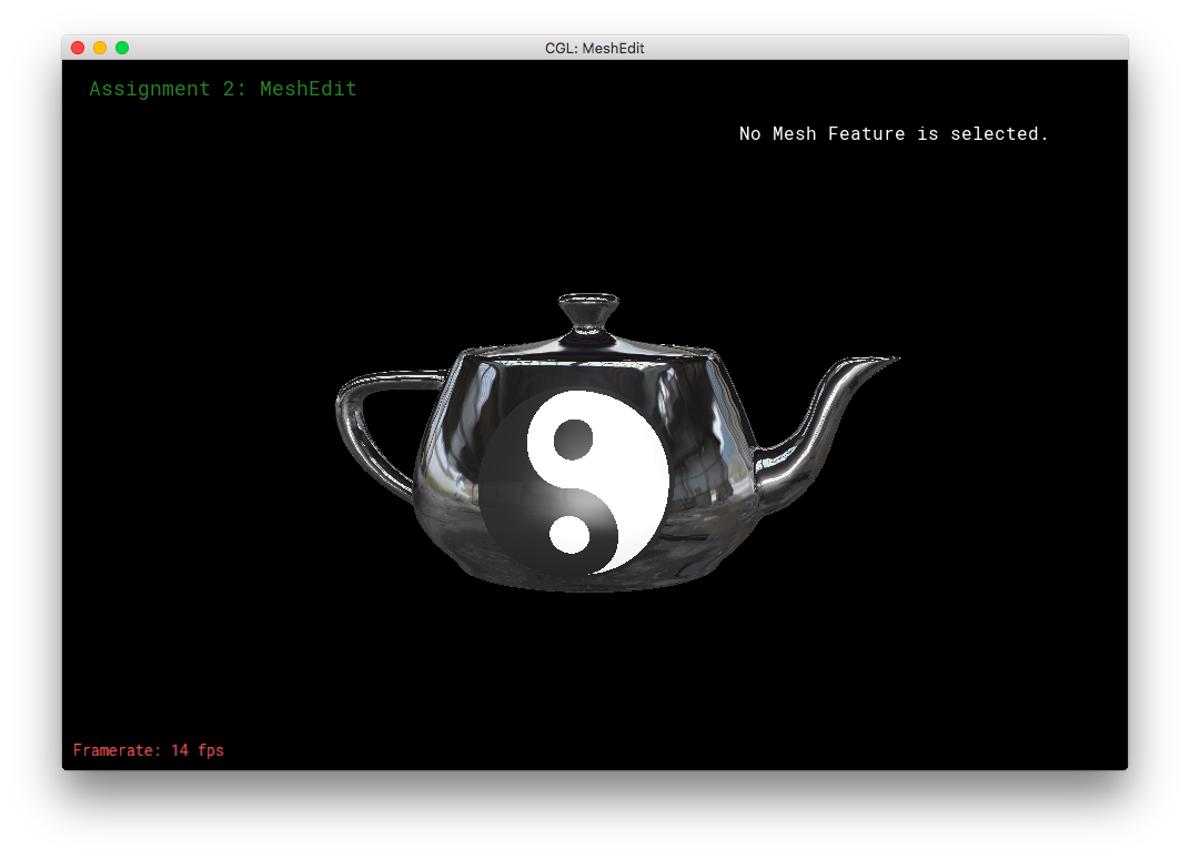
Then, I combined the Pikachu Face texture, the envMap, and the YinYang symbol onto one single teapot. Also, diffuse and specular lighting was included. To do this, I used a lot of if-statements/conditionals.
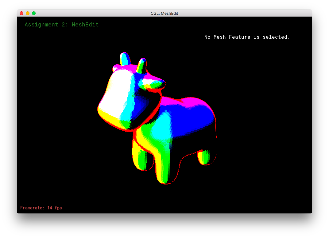
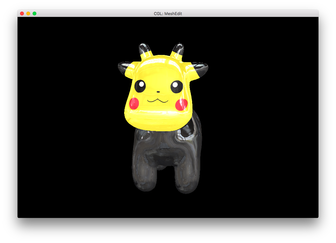
I was trying the above combo-texture/shader on different objects, when I saw an opportunity: The cow! This is yet another option available within frag.
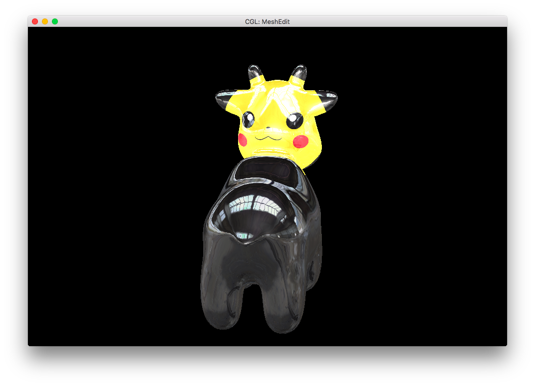
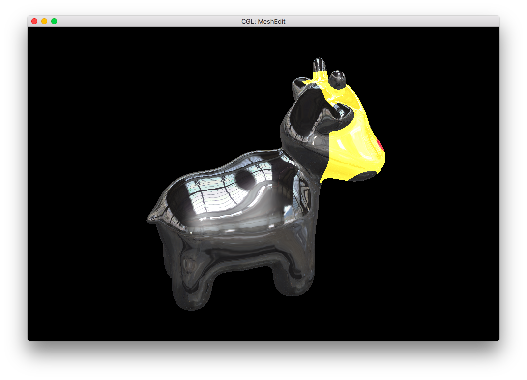
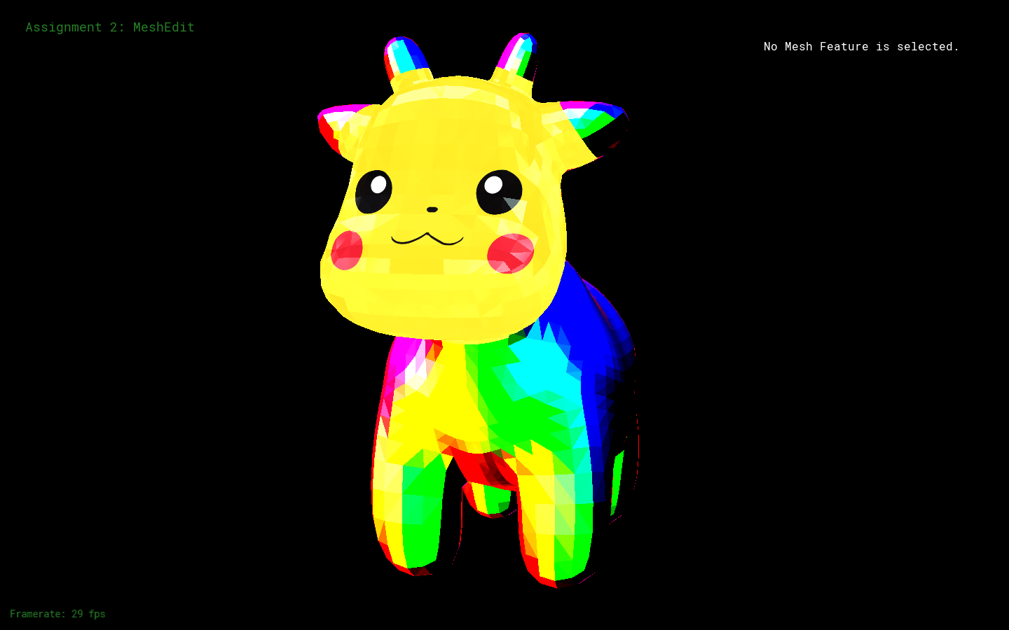
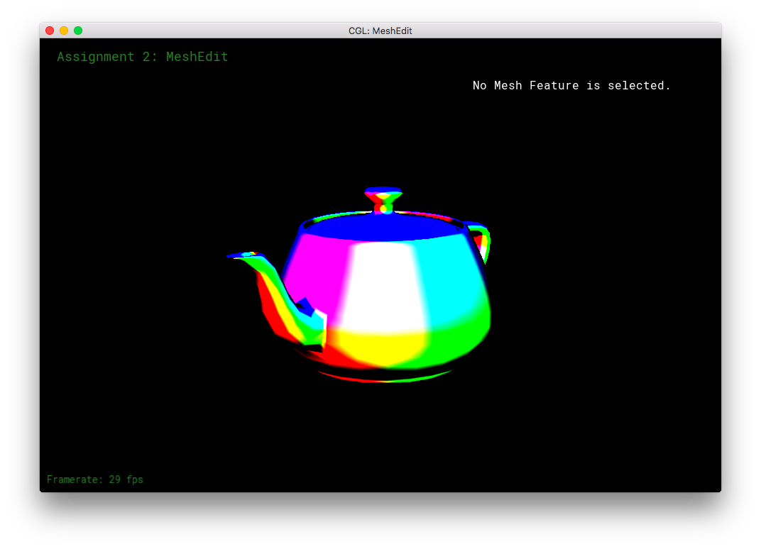
Furthermore, I reimplemented the earlier rainbow-bug of the Phong shading. But this time, it's a feature!
Finally, I combined my rainbow shader with the Pikachu-cow to get: